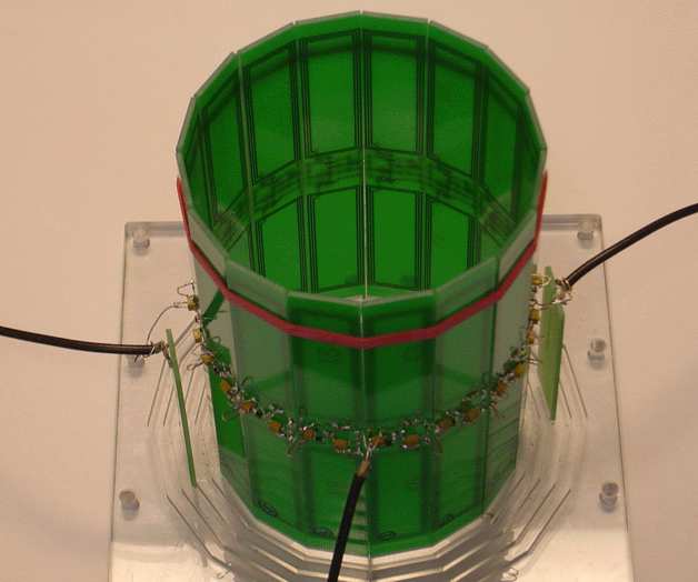
 Metamaterials from the Greek word "meta-", μετά- meaning to go beyond, are smart materials engineered to have properties that have not yet been found in nature. They are made from assemblies of multiple elements fashioned from composite materials such as metals or plastics. The materials are usually arranged in repeating patterns, at scales that are smaller than the wavelengths of the phenomena they influence. Metamaterials derive their properties not from the properties of the base materials, but from their newly designed structures. Their precise shape, geometry, size, orientation and arrangement gives them their smart properties capable to manipulate electromagnetic waves: by blocking, absorbing, enhancing, bending waves, to achieve benefits that go beyond what is possible with conventional materials. They are in essence the materials of the future.
articles
- Reflection and Refraction of Magneto-Inductive Waves
- Magneto-Inductive Waveguides with Next Nearest Neighbour Coupling
- Low-loss Magneto-Inductive Waveguides
- Thin-film Magneto-Inductive Cables
- Broad-band Coupling Transducers for Magneto-inductive Cable
- Bends in Magneto-inductive Cable
- Crosstalk in Magneto-inductive Cable
- Parasitic Coupling in Magnetoinductive Cable
- Magneto-inductive Phase-shifters and Interferometers
- Noise in Magneto-inductive Arrays
- Measuring Trapped Noise in Metamaterials
- Noise Performance of Metamaterial Cables
- Measuring Noise in Microwave Metamaterials
- Flexible Magnetoinductive Ring MRI Detector
- Parametrically-Amplified Magneto-Inductive Ring Resonators
- Parametric amplification of magnetic resonance images
- Magnetic Resonance Imaging Using Linear Magnetoinductive Waveguides
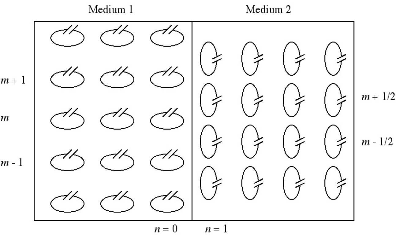
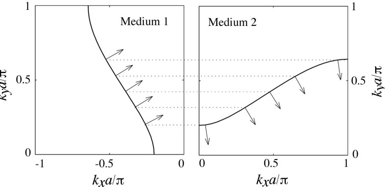
We have extended previous studies of magnetoinductive waves in homogeneous media based on resonant elements consisting of capacitively loaded metallic loops to the case when a wave is incident from one medium upon another one. The relationship between the input and output angles and the reflection and transmission coefficients have been determined with the aid of the dispersion equation for different scenarios. An expression has been obtained for the power density vector, and it has been shown that its component perpendicular to the boundary is conserved across the boundary. Using different configurations of the elements both positive and negative refraction may occur.
 |
|---|
| Boundary between two different MI wave media |
 |
|---|
| Matching of wave vectors across the boundary leading to negative refraction |
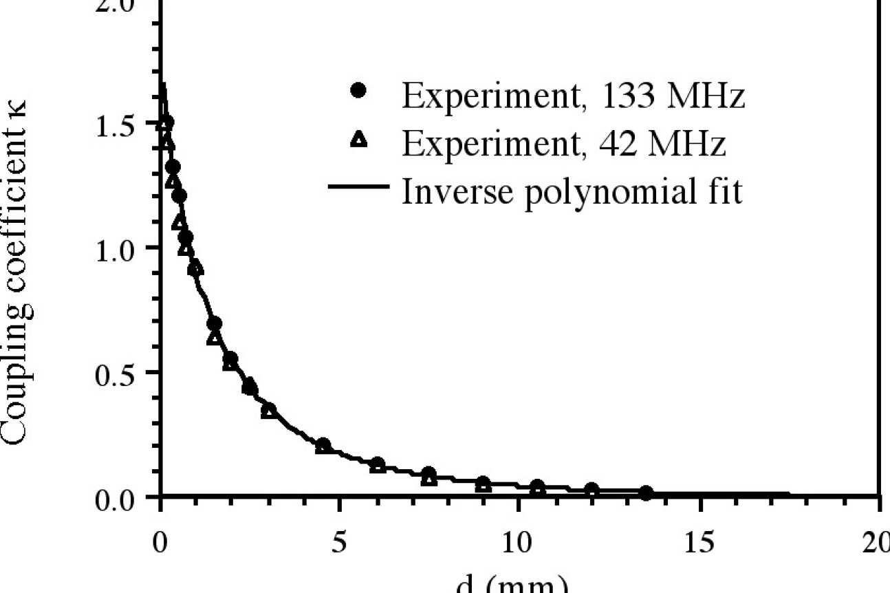
We have examined the properties of periodic chains of magnetically coupled L-C resonators supporting magneto-inductive (MI) waves in the case when non-nearest neighbour interactions are significant. The variation of the coupling coefficient with separation has been measured using resonant elements based on printed circuit board inductors and surface mount capacitors, and used to predict the S-parameters and dispersion characteristics of magnetoinductive waveguides. Good agreement with experimental measurements is obtained when higher order interactions are included. The significance of non-nearest neighbour interactions in more general MI wave devices has then been highlighted in an example problem involving reflection from a waveguide discontinuity, and the influence of higher order evanescent waves is discussed.
 |
|---|
| MI waveguide with next-nearest neighbour coupling |
 |
|---|
| Variation of coupling coefficient with axial separation |
We have developed low-loss magneto-inductive (MI) waveguides based on magnetically coupled chains of L-C resonators. The waveguides are constructed using printed circuit board inductors and external capacitors. Methods for increasing the nearest-neighbour coupling and reducing the non-nearest neighbour coupling using double-sided PCBs have been demonstrated. Conditions for low propagation loss have been determined, and a method of approximate matching to 50 Ω transmission lines has been developed. Propagation losses as low as 0.12 dB per element and coupling losses of 0.4 dBhave been achieved, using elements with Q-factors of 110 at ≈150 MHz frequency. Simple recursive Fabry-Perot filters have been demonstrated by inserting reflectors into the waveguide.
|
|
|---|
| MI waveguide based on PCB elements |
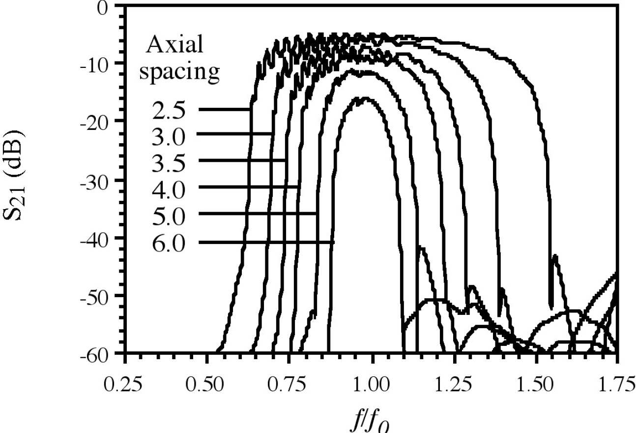 |
| Transfer characteristic of MI waveguides with different axial spacing. |
Richard Syms, Laszlo Solymar, Ian Young and Timmy Floume

Array of thin-film magneto-inductive cables with different unit cells
Magneto-inductive cables for low (ca 100 MHz) radio frequencies have been demonstrated in thin-film form. 20 cm long resonant elements have been formed using double-sided patterning of copper-clad polyimide, based on single-turn inductors and parallel plate capacitors that use the substrate as an interlayer dielectric. Continuous cables in two-metre lengths have been formed by overlaying elements, in an arrangement that allows a high, positive coupling coefficient ( > 0.6) to be achieved despite the use of a planar geometry. Equivalent circuit parameters have been extracted from experiments on integrated coupling transducers, and propagation characteristics are compared with simple theory. Low propagation loss (4 dB/m at 55 MHz, falling to 2.3 dB/m at 130 MHz) has been demonstrated near the operating frequencies of magnetic resonance imaging, for a potential application as patient-safe cable in internal imaging.
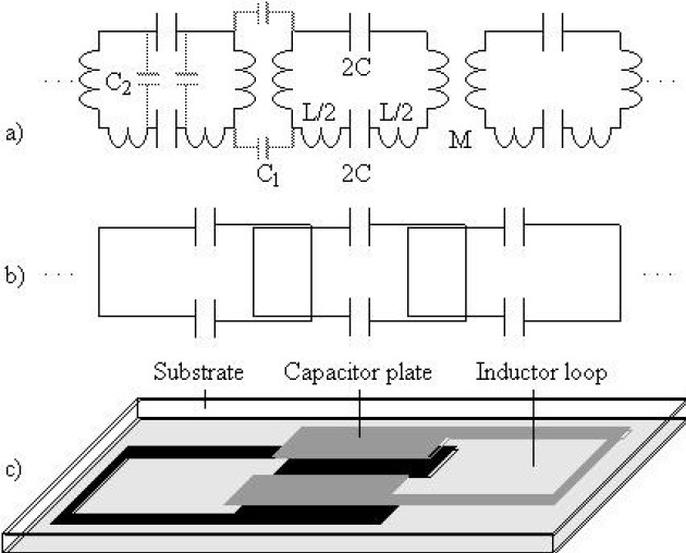
Equivalent circuit, physical arrangement and unit cell of thin-film magneto-inductive cable.
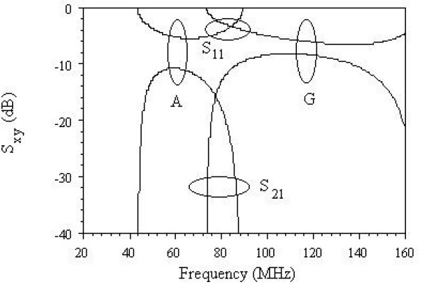 Frequency variation of S-parameters for two-metre lengths of thin-film magneto-inductive cable with different parameters
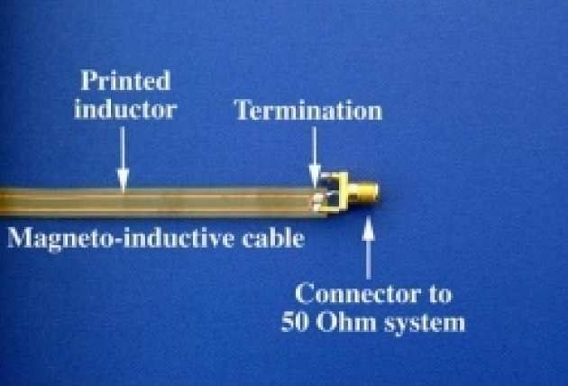
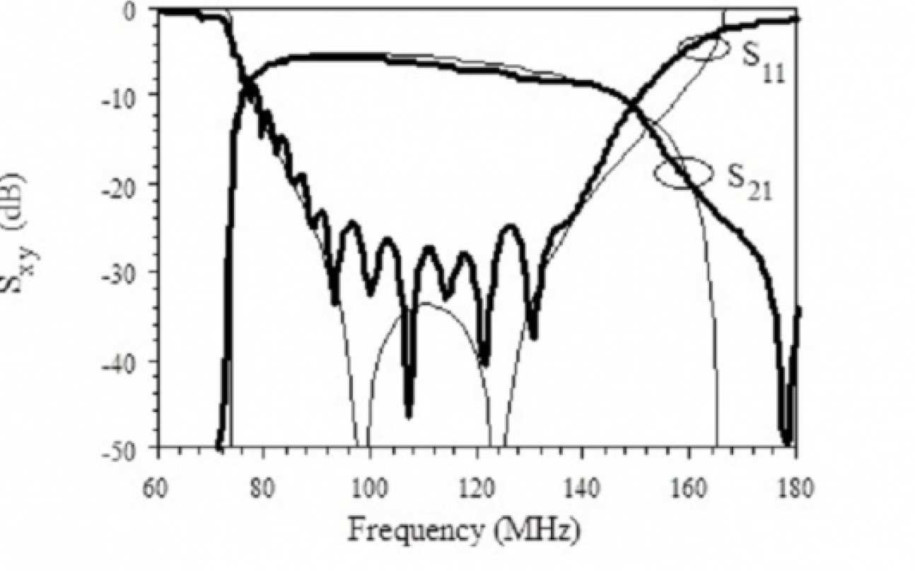
We have developed a broadband resonant transducer capable of low-loss coupling between magneto-inductive waveguides and a conventional RF system with real impedance. The transducer is an L-C circuit resonating at the resonant frequency of the elements forming the guide. However, the values of the components in the transducer are different, and chosen to obtain two separate nulls in reflection so that low reflection is obtained over a wide spectral range. The transducer can be incorporated into the MI waveguide itself, allowing a connection between a magneto-inductive cable and a conventional system to be made as a simple splice. The design has been confirmed using two metre lengths of low-loss thin-film magneto-inductive cables formed using copper-clad polyimide and operating near 100 MHz frequency.
 |
|---|
| Broad-band transducer constructed from half a resonant element in a magneto-inductive cable. |
 |
|---|
| Experimental realisation of a broad-band transducer for magneto-inductive cable. |
 |
|---|
| Comparison between experimental and theoretical performance of a broad-band transducer. Low reflectivity is obtained over most of the magneto-inductive band. |
We have investigated the effect of waveguide bending on the propagation of MI waves, and have shown that discontinuities in axis curvature will typically generate reflections.
Changes in the equivalent circuit parameters of two types of MI waveguides (formed from discrete elements and continuous cable, respectively) at abrupt bends have been identified, and simple formulae have been developed for the reflection and transmission coefficients in each case.
We have shown that thin-film MI cable can outperform MI waveguides formed using separate elements, due to the inherent stability of the mutual inductance, and can tolerate extremely tight bends. The theory has been confirmed using experiments carried out using thin-film cable operating at 100 MHz frequency.
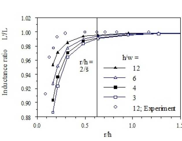
Variation of normalised inductance with normalised bend radius for magneto-inductive cable. The self-inductance (and hence also the mutual inductance) is broadly constant until the bends become very tight.
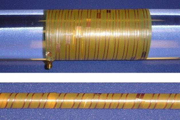
Magneto-inductive cable in a spiral winding around cylindrical formers of radii as small as 5 mm.
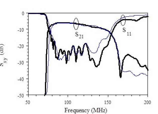 Frequency variation of S-parameters in two-metre lengths of straight cable (black line) and spiral-wound cable with 5 mm radius (blue line).
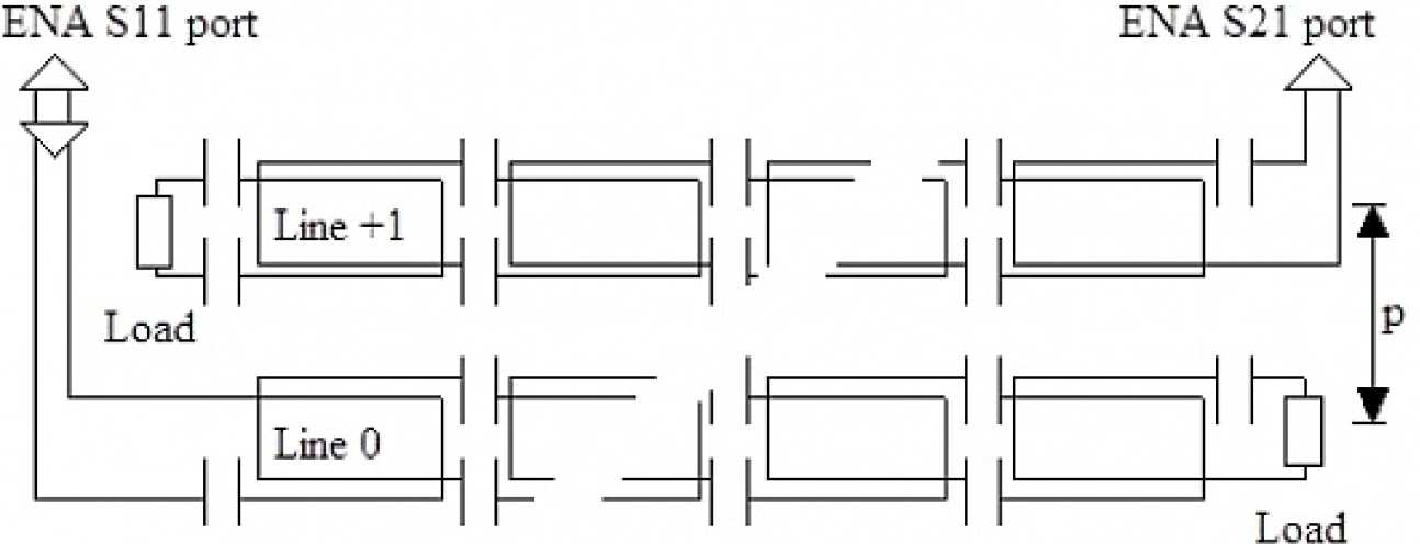
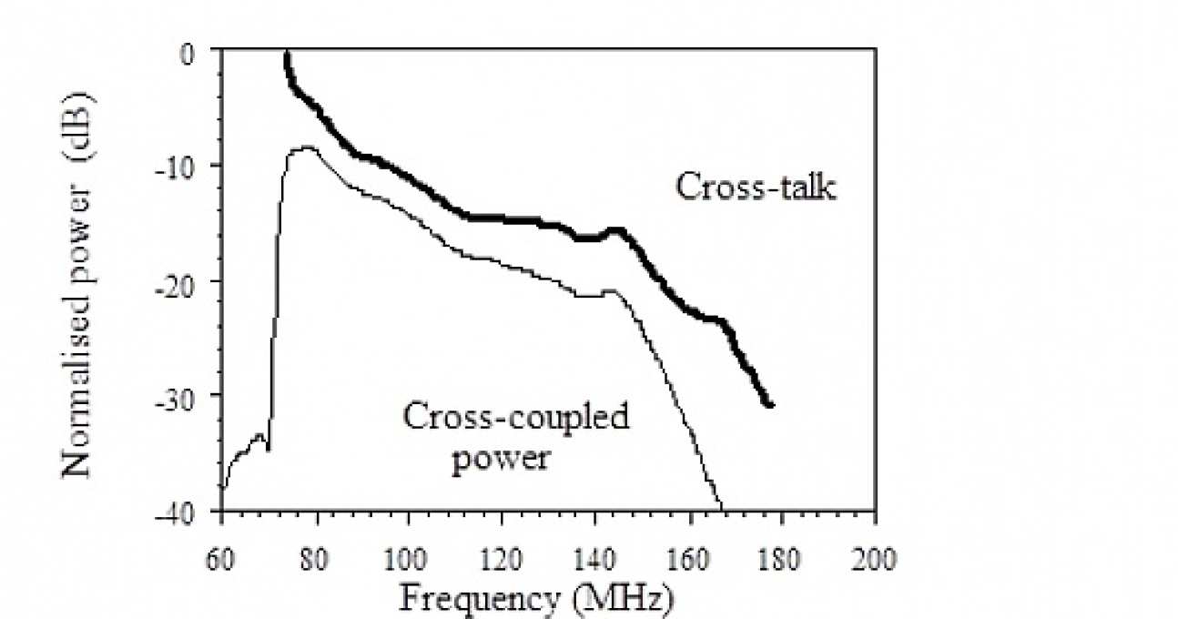
We have investigated the properties of cable arrays formed from a set of parallel magneto-inductive lines, which might be expected to suffer from crosstalk due to the spread of magnetic fields between adjacent cables. We have calculated the mutual inductance numerically for typical arrangements. We have developed analytic methods for estimating the coupling between elements in neighbouring cables and the frequency dependence of cross-talk. Theoretical confirmation has provided by experimental results for cables operating at ≈ 100 MHz. Strategies for reducing cross-talk using alternative element designs that achieve low mutual inductance by cancellation of induced currents have been explored.
 |
|---|
| Broadside-coupled magneto-inductive cables. |
 |
|---|
| Experimental arrangement for measurement of crosstalk in magneto-inductive cable. |
 |
|---|
| Frequency-variation of cross-coupled power and normalised cross-talk between paired cables |
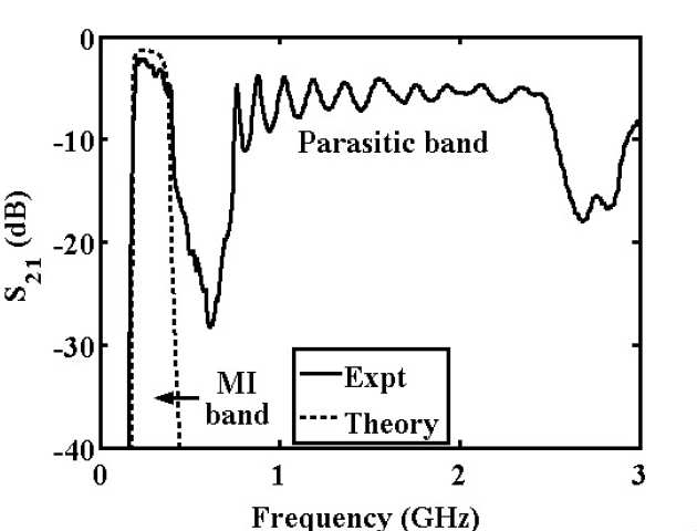
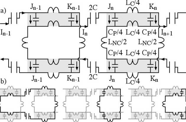
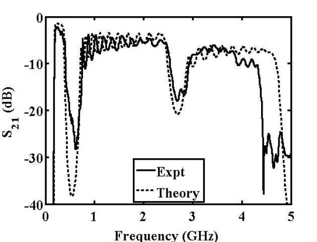
Magneto-inductive (MI) waveguides are linear arrangements of magnetically coupled L-C resonators that propagate electrical energy at radio frequency without direct connection. To achieve the strong magnetic coupling needed for low-loss propagation, adjacent elements must be in such close proximity that electric coupling arises. In contrast to electric coupling in split ring resonators, the coupling occurs between the inductive tracks of adjacent resonant loops. Parasitic capacitance has been demonstrated in flexible magneto-inductive cable, and shown to introduce additional propagation bands above the MI band. Simple models have been developed to predict this effect, and strategies discussed to improve high-frequency isolation.
-waveguides-Image1--tojpeg_1498124402702_x2.jpg) |
|---|
| a) Plan and b) section view of MI cable; c) approximate cross-sectional geometry. |
 |
|---|
| Comparison of the experimental frequency variation of S21and the predictions of the standard magneto-inductive model, showing a parasitic propagation band at high frequency. |
 |
|---|
| a) Equivalent circuit of MI cable, including two parasitic capacitors for each coupled track section; b) closed loops used to develop circuit equations. |
 |
|---|
| Comparison of the experimental frequency variation of S21with the predictions of the new model with 16 parasitic capacitors per coupled track section. |
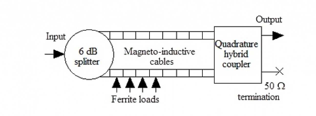
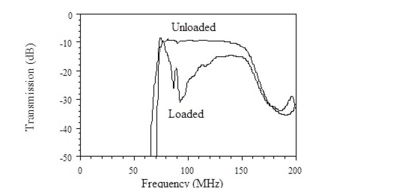
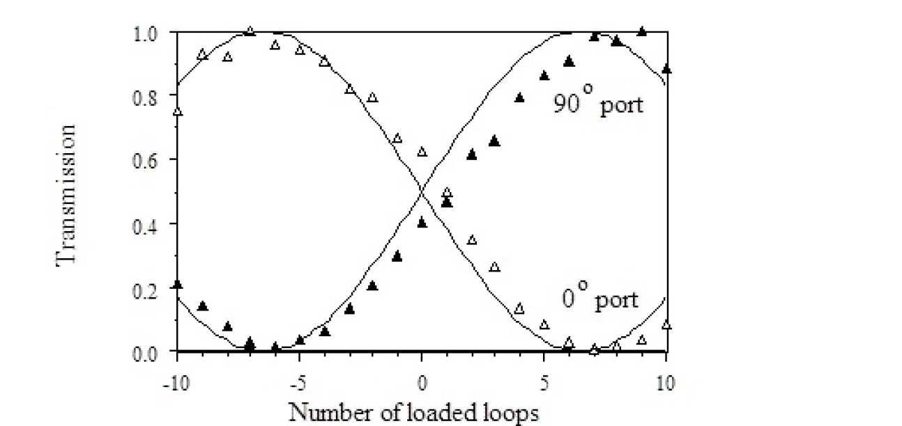
We have demonstrated controllable phase shifting of magneto-inductive waves by ferrite loading of magneto-inductive waveguides. Ferrite loading reduces the resonant frequency in isolated resonators and lowers the pass-band in waveguides. We have developed simple theory to estimate the dependence of the phase shift on the perturbed waveguide parameters and wavelength, and confirmed its predictions using experiments carried out using thin film L-C resonators and thin-film magneto-inductive cable operating near 100 MHz frequency. Phase shifts are converted into amplitude changes by interference of magneto-inductive waves in Mach-Zehnder interferometer structures analogous to those used in guided wave optics, using conventional RF components for beam splitting and recombination. We have demonstrated modulation and space switching, and shown that in each case the variation of output power with phase shift follows the conventional sinusoidal characteristic.
 |
|---|
| Magneto-inductive Mach-Zehnder interferometer. |
 |
|---|
| Frequency variation of transmission with and without ferrite loading on one arm of a magneto-inductive Mach-Zehnder interferometer. |
 |
|---|
| Variation of transmission from the two output ports of a Mach-Zehnder interferometer with the number of loaded elements. The full lines show best fits to cosinusoidal variations. |
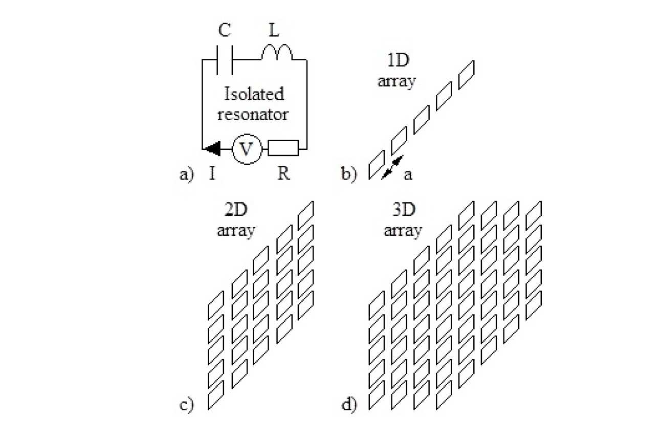
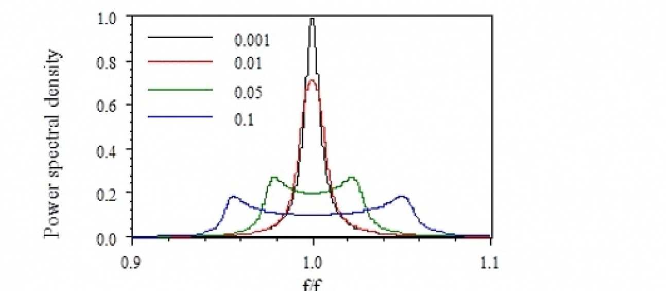
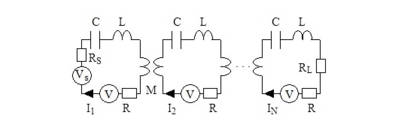
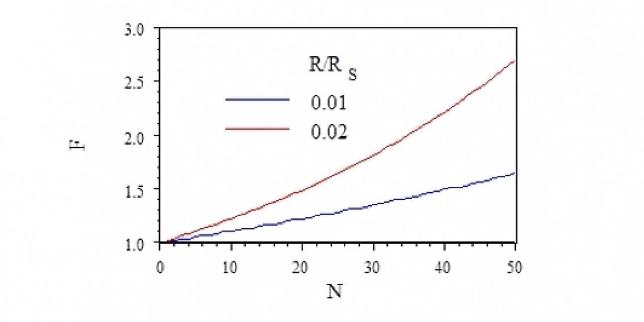
Metamaterials made up of resonant elements containing lossy metallic conductors will invariably give rise to Johnson noise. We have developed a model based on nearest neighbour interaction of magnetically coupled elements, which predicts the propagation of noise waves and the excitation of resonances in regular arrays. We have calculated the power spectral density (PSD) of the noise for rectangular arrays of different dimension, and have shown that the effect of coupling is to alter the PSD, spreading the noise over the whole magneto-inductive bandwidth. The implications for passive and active devices have been examined using the simple model of a lossy one-dimensional interconnect with distributed parametric amplification, and it has been shown that the improvements to the noise factor offered by amplification are limited.
 |
|---|
| Magneto-inductive arrays of different dimension, with embedded Johnson noise sources. |
 |
|---|
| Frequency variation of normalised power spectral density of noise in 1D arrays with different coupling coefficients between the elements. |
 |
|---|
| Magneto-inductive link with embedded noise sources |
 |
|---|
| Variation of noise factor F with number of elements N in the line, for noisy magneto-inductive waveguides with different loop resistances. |
Metamaterials constructed from conductive elements are lossy, and the structures act as sources of noise, whose spectrum is modified by the resonant nature of the medium itself. Furthermore, inside the medium, the noise is present as waves, which are standing waves for finite length samples. We have obtained direct measurements of the noise spectra for a simple metamaterial that consists of arrays of LC resonator elements, and compare them with the predictions of a circuit model incorporating Johnson noise. We have found excellent agreement between the measured data and the model, reproducing both the resonant structure and the bandwidth of the noise spectrum, thus confirming the concept of noise waves in these metamaterials. These noise features match the frequency ranges where the metamaterial properties are useful, showing that noise is an inevitable companion to metamaterial performance in practical situations.
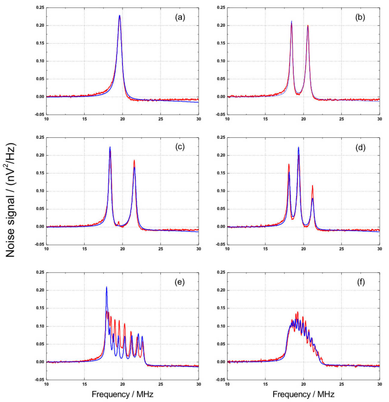 |
|---|
| Comparison of measured and calculated excess noise spectra in nV2 / Hz as a function of frequency for (a) a single element, (b) a pair of elements, (c) a triplet of elements, sampled at the centre, (d) a triplet of elements at the end, (e) a line of 19 elements, sampled at the centre, (f) a line of 19 elements, sampled at the end. Full red line, measured noise; dashed blue line calculated noise spectra. |
Mike Wiltshire and Richard Syms
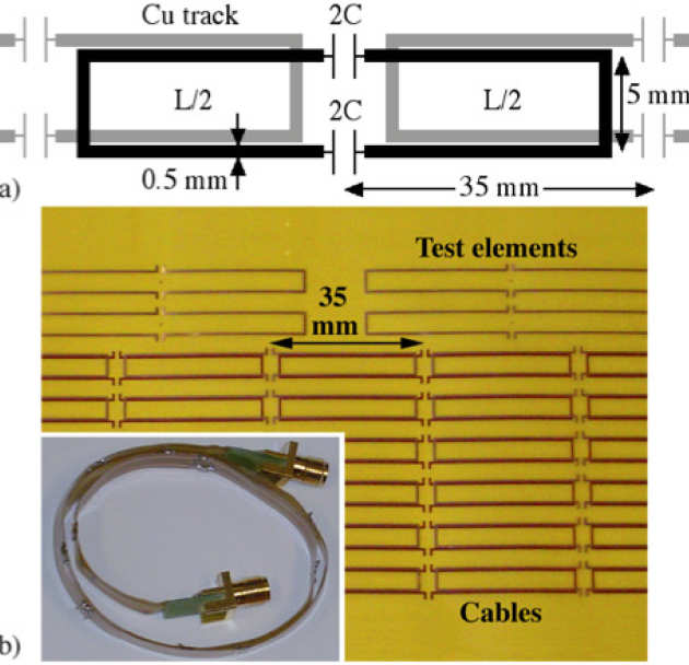
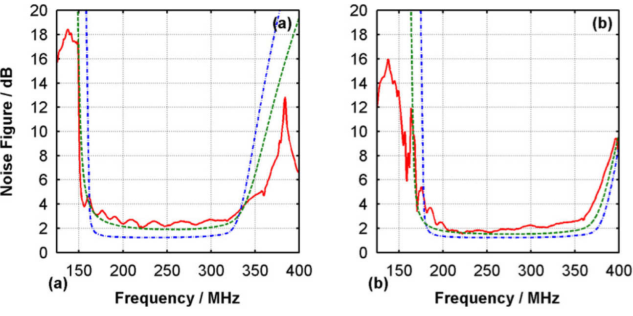
Magneto-inductive (MI) waveguides are metamaterial structures based on periodic arrangements of inductively coupled resonant magnetic elements. They are of interest for power transfer, communications and sensing, and can be realised in a flexible cable format. Signal-to-noise ratio is extremely important in applications involving signals. We have made the first experimental measurements of the noise performance of metamaterial cables. We have focused on an application involving RF signal transmission in internal magnetic resonance imaging (MRI), where the subdivision of the metamaterial cable provides intrinsic patient safety. We consider MI cables suitable for use at 300 MHz during 1H MRI at 7 Tesla, and find noise figures of 2.3 – 2.8 dB/m, together with losses of 3.0 – 3.9 dB/m, in good agreement with model calculations. These values are high compared to conventional cables, but become acceptable when (as here) the environment precludes the use of continuous conductors. To understand this behaviour, we have presented arguments for fundamental performance limitations in metamaterial cables.
 |
|---|
| a) Layout and b) flexible circuit board for magnetoinductive cable. |
 |
|---|
| Noise figure (dB) spectra for the two MI cables: (a) Cable 1, 80mm loops; (b) Cable 2, 70 mm loops. Red, full lines are measured spectra; blue, dash-dot lines are spectra calculated with the basic cable parameters; green, dash lines are calculated with allowance for parasitic capacitance and dielectric loss. |
Mike Wiltshire and Richard Syms
Electromagnetic metamaterials are artificially constructed media composed of arrays of electrical circuits that can exhibit electric and magnetic characteristics unlike those of any conventional materials. However, the materials are lossy and hence noisy, so that the signal-to-noise ratio in practical situations is greatly reduced. In particular, operating in the double negative region, where both the permittivity and permeability are negative so the refractive index is real but negative, incurs significant loss and noise penalties. We have carried out noise measurements on a double negative metamaterial at microwave frequencies, and compared them with the results of a simple model based on a transmission line loaded with lossy elements that mimic the split ring resonators and fine wires of the metamaterial. A noise source is associated with the resistive part of each element, and these are added incoherently to predict the total noise spectrum of the metamaterial. The theoretical results are in good agreement with the measurements. In particular, we find that the measured noise spectrum has contributions from both electric and magnetic noise, but is dominated by the magnetic noise. This limits possible applications, even with optimised materials, to functions that cannot be realised by conventional means.
 |
|---|
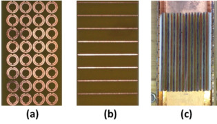
| Components used to construct the metamaterial: (a) SRR, (b) wires, and (c) 12-unit cell CMM material, with alternate layers of SRRs (red) and “wires” (blue) spaced by Rohacell sheets, mounted in the waveguide. |
 |
|---|
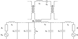
| Transmission line circuit model of a metamaterial. Free space is represented by the L0, C0 line, terminated by Z0; the wires contribute a shunt inductance LW, and the rings are represented by LR, CR, and are mutually coupled by M, and coupled to the line by MR. Each lossy component contributes a noise voltage (not shown). |
 |
|---|
| Transmission line model after abstraction. The noise in each unit cell is represented by VR and IW for the rings and wires respectively; the rings contribute to the effective permeability, whereas the wires contribute the effective permittivity, ε. |
 |
|---|
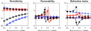
| Transmission line model calculation, showing the permittivity, permeability and refractive index spectra for the 6-cell samples with parameters f0 = 4.68 GHz, F = 0.23, Q0 = 35, γe = 0.15, with fp = 12.5 GHz for the wires alone, and 8.5 GHz for the CMM. The magneto-electric coupling parameter is k = 0.05 for the SRRs alone, and 0.19 in the CMM. Full lines show real parts for wires (blue r), rings (red s) and CMM (black ô), dotted lines show imaginary parts for wires (blue +), rings (red x) and CMM (black *). |
 |
|---|
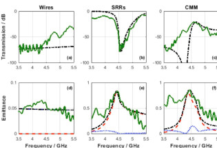
| Comparison of the measured and modelled transmission spectra (a-c); and comparison of measured noise power with calculated emittance (d-f) for (left to right) wires, rings and CMM. Green full lines show measured data, black chain lines are calculated, with red dashed lines the magnetic contribution and blue dotted the electric contribution to the noise power. |
Richard Syms, Timmy Floume, Ian Young, Laszlo Solymar and Marc Rea (St Mary's)
 |
|---|
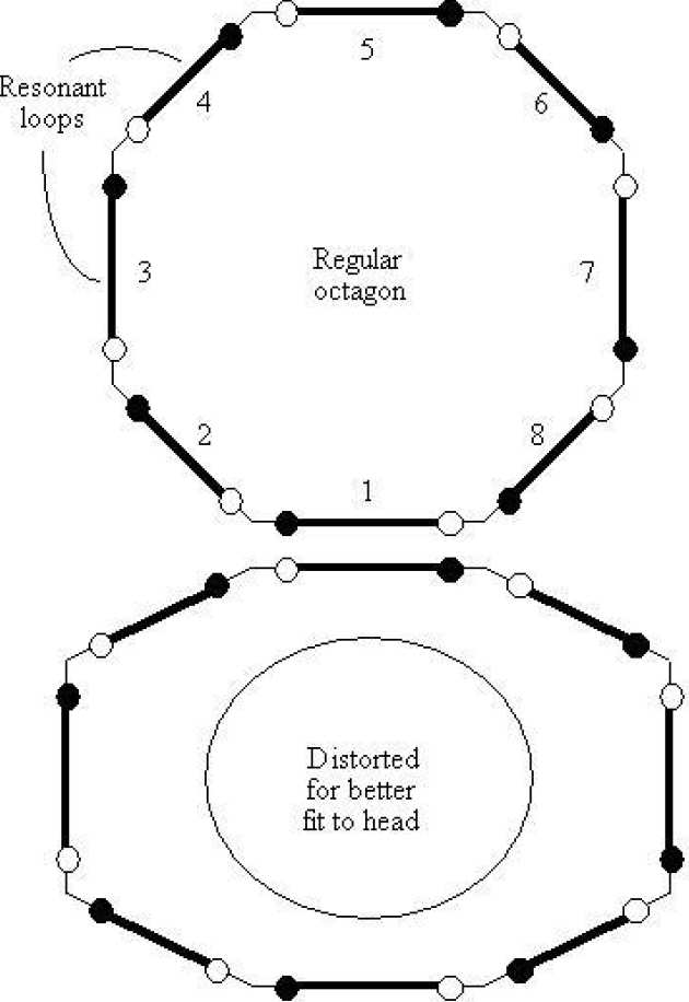
| Principle of flexible octagonal MRI detector |
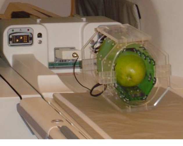
We have developed a flexible birdcage-type resonant RF detector for magnetic resonance imaging, to allow an improved match to the human head. The circuit consists of a polygonal ring of magnetically coupled L-C resonators, a periodic structure supporting backward magneto-inductive waves. The elements are mechanically linked to allow relative rotation, and the pivot point is optimised to hold the nearest neighbour coupling coefficient invariant to small changes in the angle of an undistorted joint. Simple theory based on a parallel wire approximation to rectangular inductors has been developed to allow the variation of the coupling coefficient with angle and radius to be estimated, and hence determine the location of the pivot. The optimised pivot has been shown to reduce resonance splitting in octagonal rings. The theory has been verified experimentally using printed circuit board elements coupled by flexible hinges, and the invariance of the nearest neighbour coupling coefficient has been confirmed. Octagonal ring resonators have been constructed for operation at 63.8 MHz frequency and the mode spectra of regular and distorted rings have been measured. Imaging properties have been investigated using 1H MRI of simple objects in a1.5 T field.
 |
|---|
| 1H imaging of a pomelo fruit using the flexible coil at 1.5 T in a GE Signa Excite scanner |
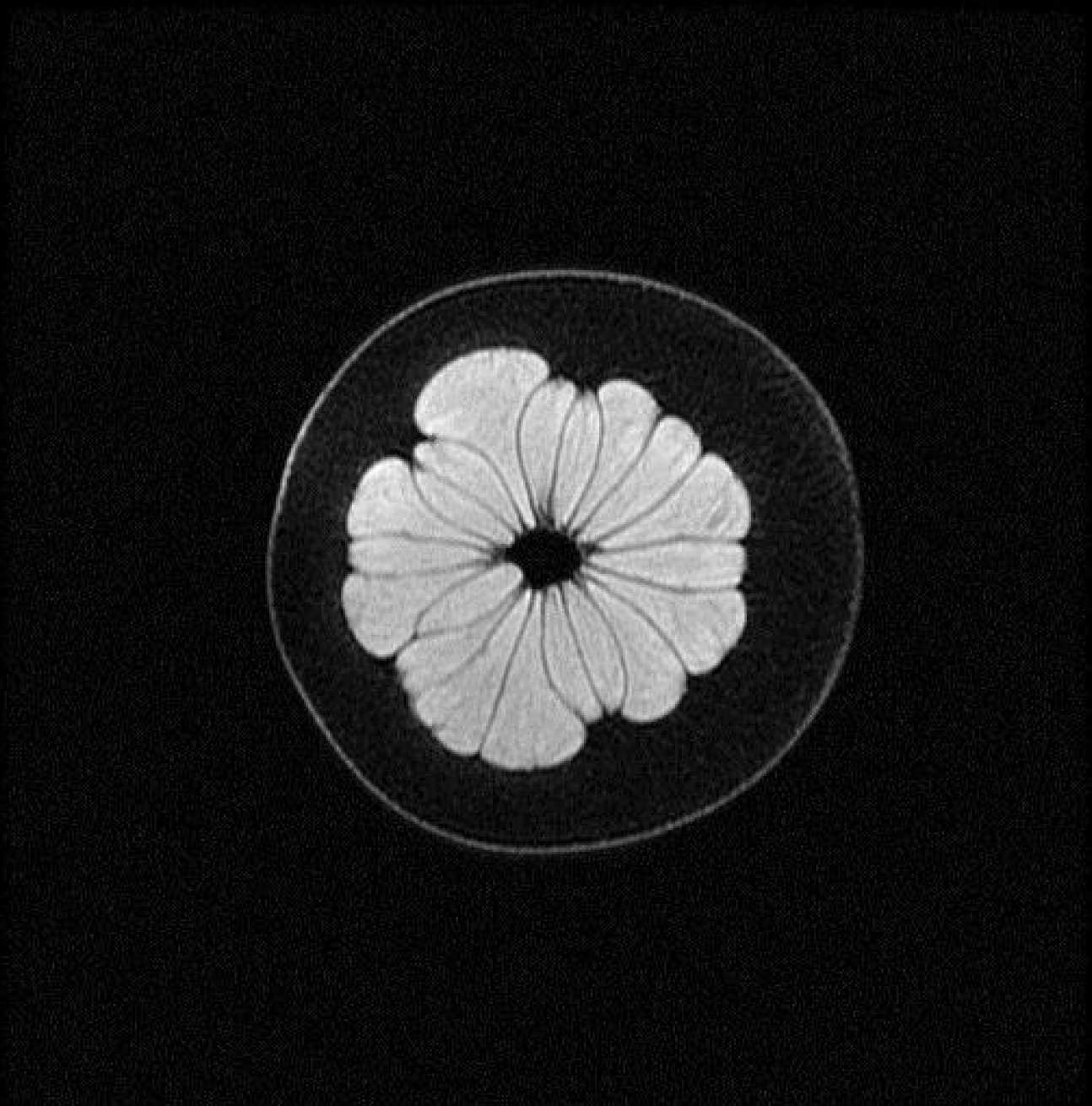 | |
|---|---|
| 1H MR images of pomelo fruit with coil octagonal (LH) and distorted (RH) | |
Richard Syms, Laszlo Solymar, Ian Young
We have demonstrated parametric amplification of magneto-inductive waves in magnetically coupled chains of non-linear L-C resonators. Analysis has been developed for a three-frequency travelling wave scheme in which the signal, idler and pump all propagate as MI waves. The effect of de-coupling the idlers has been considered and it is shown that this configuration relaxes the standard phase matching condition. Confirmation of the theory has been provided using low-frequency PCB unit cells containing varactors, which are arranged as a 16-element ring. Frequency matching and selective amplification of the primary resonance has been demonstrated. The primary resonance can be excited using the field of a rotating magnetic dipole, and an application in MRI is being considered.
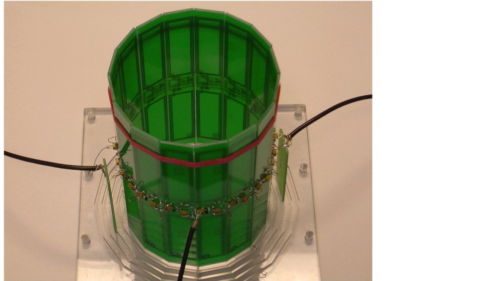
Parametrically amplified MI ring resonator
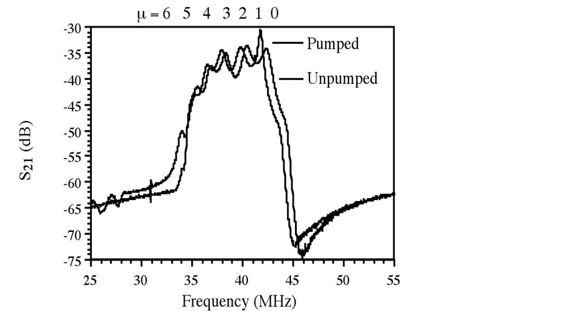
Transfer characteristics of ring, with and without pumping of the primary resonance
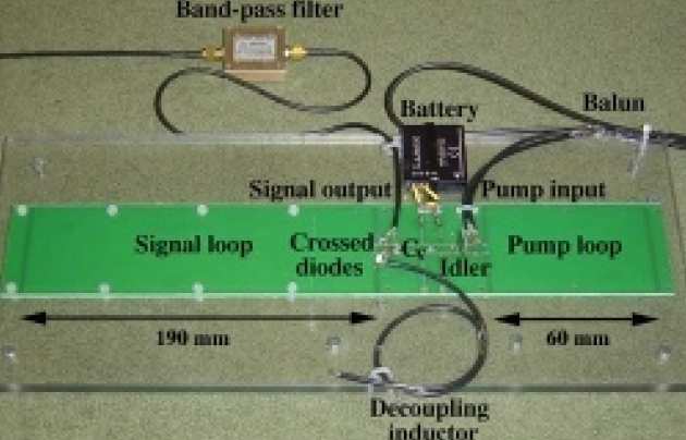
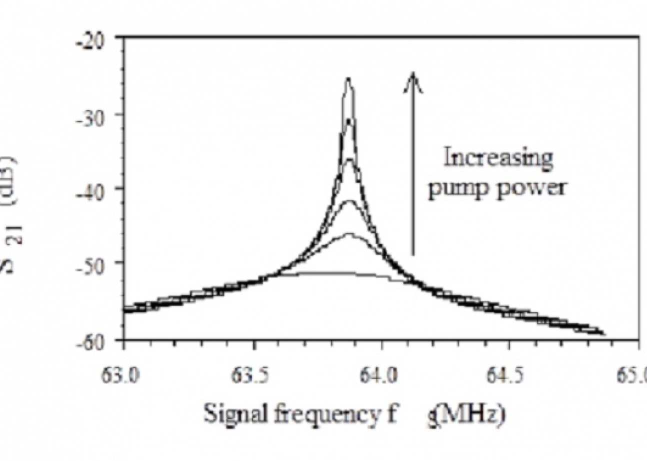
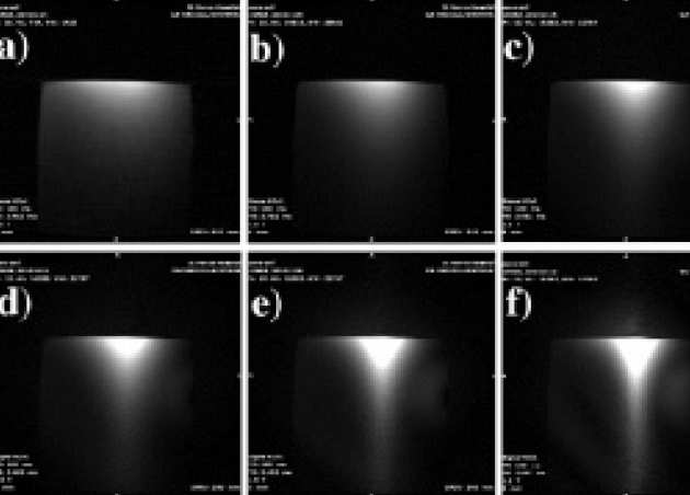
We have investigated parametric amplification as a method for detecting magnetic resonance imaging (MRI) signals. We have converted a three-frequency amplifier circuit into an amplified surface coil for operation at 63.85 MHz, inserting appropriate TX protection to allow 1H MRI at 1.5 T field. Electrical characterization has been carried out, and good agreement obtained with theory. The Q-factor is controllable and the amplifier is frequency-tunable. A linear gain of 100 (corresponding to 40 dB power gain) and a Q-factor of 18,000 have been demonstrated. Imaging of phantoms has been carried out, and frequency-domain filtering of images and controllable shifting of the field of view have been demonstrated.
 |
|---|
| Experimental realisation of parametrically amplified detector |
 |
|---|
| Frequency variation of amplifier response at different pump powers |
 |
|---|
| Phantom images at different pump powers. |
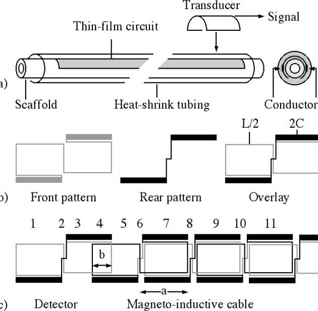
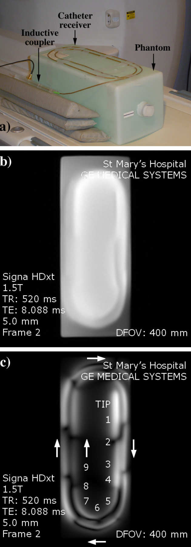
Magneto-inductive waveguides are arrays of magnetically coupled, lumped element resonators, which support slow waves at radio frequency. We have demonstrated their use in internal magnetic resonance imaging (MRI), where they may provide an intrinsically safe method of signal detection and transmission. A catheter-based receiver formed from a thin-film printed circuit mounted on a tubular scaffold using heat-shrink tubing has been demonstrated, and its electrical response and imaging sensitivity explained in terms of the excitation and propagation of magneto-inductive waves. The theoretical predictions have been confirmed using the results of electrical measurement and 1
H MRI at 1.5 T, and imaging has been achieved over a total length greater than 1.5 m using a single receiver. Potential applications include arterial and biliary imaging.
 |
|---|
| a) Construction of magneto-inductive catheter receiver, b) conductor layout for a single resonator, and c) layout of overall thin film circuit. |
 |
|---|
| a) Arrangement for 1H magnetic resonance imaging at 1.5 T; b) and c) coronal MR images obtained using the body coil and magneto-inductive catheter receiver. |
 able's contents