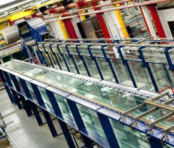
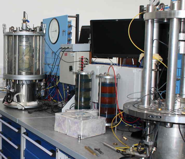
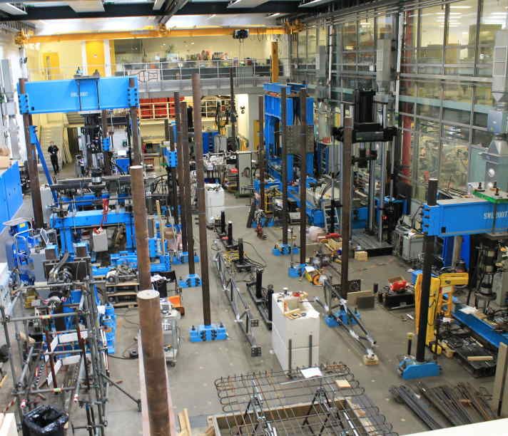
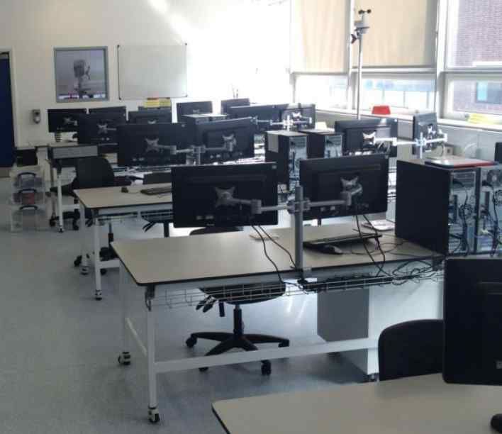
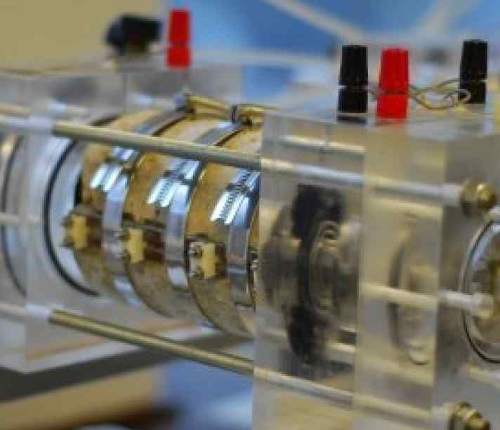
The laboratories of the Department of Civil and Environmental Engineering provide state-of-the-art facilities and are amongst the most up-to-date and best equipped in Europe. The laboratories house a wide range of facilities available for research, teaching and consultancy. We have five labs, all of which have been fully rebuilt or substantially refurbished within the past seven years. In addition, the Department has outstanding computing facilities. These complement the facilities provided by the College and provide a very supportive environment for research and study.
Our Laboratories
Each research section has its own dedicated state-of-the-art research laboratory
| A-C | D-N | O-Z |
|---|---|---|
|
Biaxial Internal Reaction Frame Compression Rig + Hoek-type Triaxial Cell Compression Testing Rig Computing Facilities Concrete Durability Equipment (Exposure Lab) Concrete Durability Equipment (Microstructure Lab) Concrete Durability Equipment (Transport Lab) Concrete Durability Group (Chemistry Lab) Concrete Durability Lab (Porosity Lab) Creep Rigs |
Data Acquisition Equipment Dynamic/Pseudodynamic Testing Equipment Fixing Rig Flumes and Wave Tanks Heavy Scale Testing Frames High Temperature Strength Testing Rig High-stress Triaxial Apparatus Hollow Cylinder Apparatus Impact Rig MAYES Tension/Compression Machine |
Oblique Fixing Rig Random Wave Generators Ring Shear Apparatus Roger Perry Environmental Engineering Laboratory Scanning Electron Microscope Servo Hydraulic Loading Equipment Strong Floors Tension/Compression Rig Triaxial Testing Equipment |
Research Spotlights
The drop downs below highlight how our laboratory facilities have been used to provide experimental data to validate research findings.
Spotlights: How the laboratories have been used to provide experimental data to validate research findings
- Validation data for predictive methods being applied to the behaviour of coastal armour units
- Study of early-age and long-term cracking in reinforced concrete walls with base restraint and with combined base and end restraint
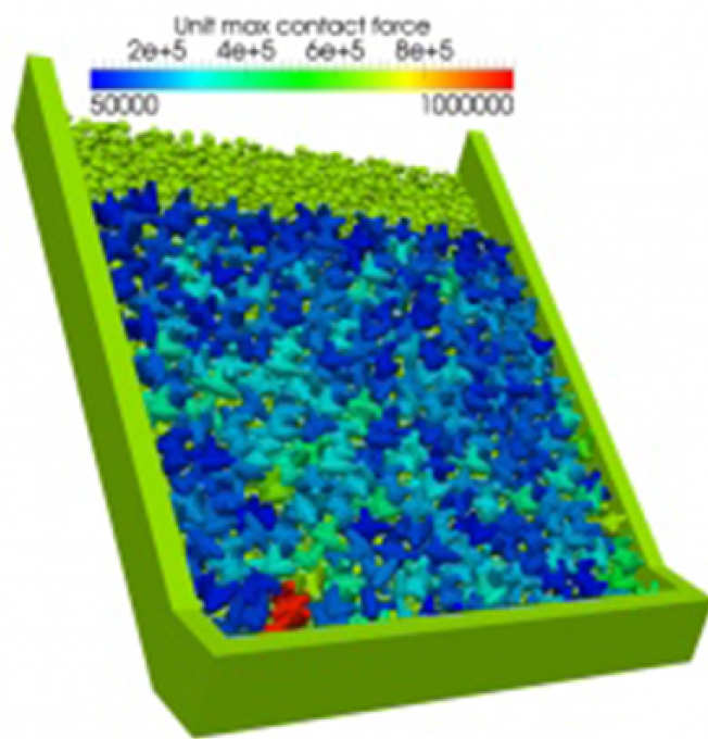
Massive concrete armour units are used extensively around the world in harbour breakwaters and coastal defences. A range of experiments are being carried out in the Structures Laboratory, to support the development and validation of computational methods (in the Department of Earth Science and Engineering http://vgest.net/applications/coastal-engineering/stresses-in-armour-units/ ) aimed at predicting the behaviour of multi-body systems comprising such units in the loading regimes typically experienced in reality. In-elastic models including plastic and fracture behaviour are being introduced into the computational models.
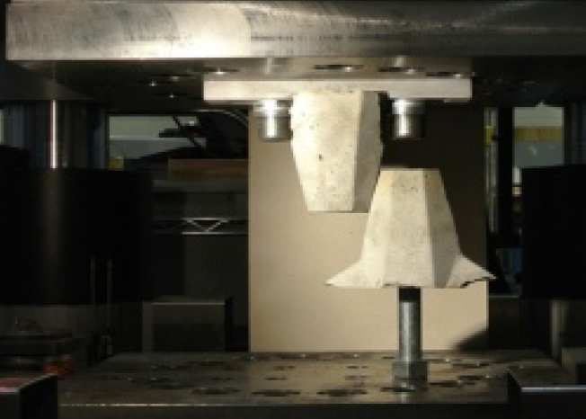
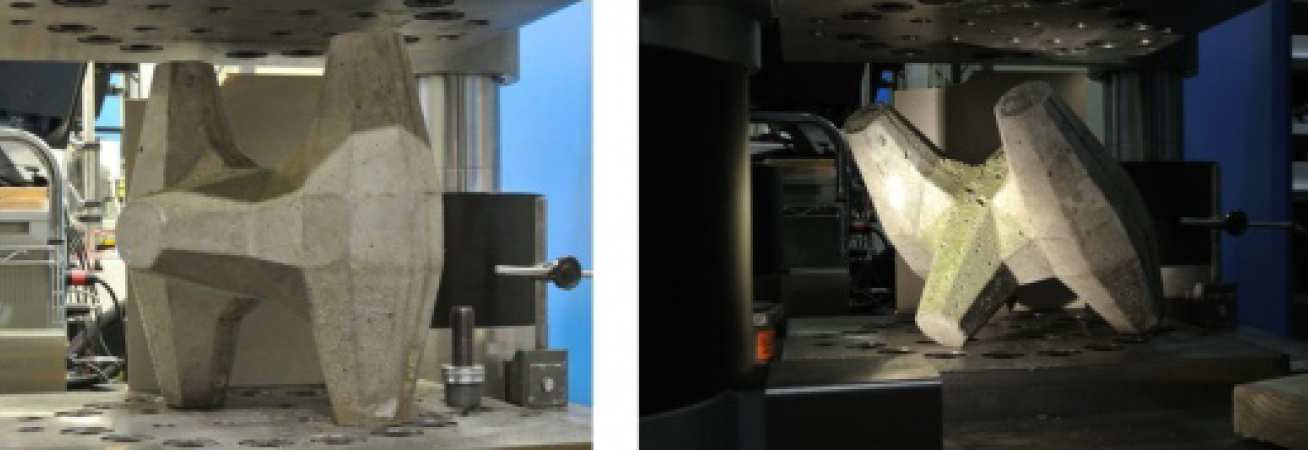
The real armour units in use today have a range of shapes and are typically 2.5 to 4.5m high, weighing between 15 and 60 tonnes. The laboratory test programme is using scale models (around 1/8 and 1/50). For example, these 350mm high units will be loaded in compression in a 3500KN capacity servo-hydraulic test rig, in both four-point and six-point loading configurations.
Individual “arms” have been cast onto rigid mountings to allow the frictional and damage characteristics of interactions between units to be assessed.
Contacts:
Department of Civil and Environmental Engineering;
- Andy Pullen, Structures Laboratory;a.pullen@imperial.ac.uk
- Professor Bassam Izzuddin, b.izzuddin@imperial.ac.uk
Earth Science and Engineering;
- Dr John-Paul Latham, j.p.latham@imperial.ac.uk
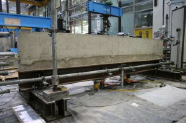
In practice, when casting concrete elements on site, it is difficult, if not impossible, to avoid having any form of restraint whatsoever, which is a potential cause of cracking. Example applications include (but are not limited to) reinforced concrete (RC) walls cast on stiff foundation bases (base restraint) and RC wall panels cast between previous pours on a stiff base (combined edge and end restraints) such as in retaining walls, liquid-retaining tanks and underground structures including tunnels.
Cracking in RC structures is problematic not only because it jeopardises aesthetics and durability but also because it may cause water leakage problems in liquid-resisting structures. Crack widths may, however be controlled by steel reinforcement.
A series of tests are carried out in the Structures Laboratory within the Department of Civil and Environmental Engineering at Imperial College London to investigate parameters affecting cracking and crack widths in walls with base restraint and with a combination of base and end restraints. Tested walls are typically 3.5m long and vary in height between 0.5 and 0.75m. Steel fixing as well as concrete mixing and casting is carried out by qualified laboratory technicians in the Structures Laboratory. Following casting, the RC walls are monitored for cracking during early age thermal contraction and long term shrinkage. In addition, quality control tests such as cube and cylinder strength tests are also carried out within the Structures Laboratory.
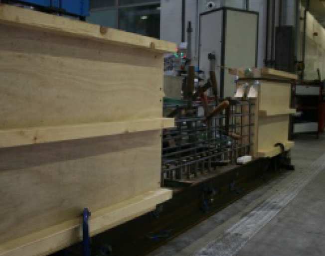
Temperatures are constantly monitored using thermocouples cast within the concrete. Transducers monitor horizontal and vertical wall displacements whereas DEMEC strain gauges and electric strain gauges are used to monitor compressive and tensile strains in the RC wall and restraining steel beam. Cracks are monitored and crack widths measured using a crack width microscope.
Preparation for casting the ends of a wall with combined restraint
Test results are being used to validate numerical models in ADAPTIC. Once validated, more parameters may be investigated using these validated models.
- PhD candidate: Marianna Micallef
- Laboratory technician: Leslie T. Clark
- Supervisors: Dr Robert L. Vollum; Professor Bassam A. Izzuddin
- Project funding: Laing O’Rourke
Hiring these facilities
All our facilities are made available to industry for testing, evaluation and developmental work.
Contact Lindsey Anne Cumming, Departmental Operations Manager, Department of Civil and Environmental Engineering
