Indexing Data with HKL-3000
Go to the Data tab. If you've just collected, the data are loaded already. If you want to process old data, select the data and processing directories as shown in the figure below. Clicking Load Data Sets gives you a list of dataset in the chosen directory. Pick those that you want to process in one go.
Indexing data
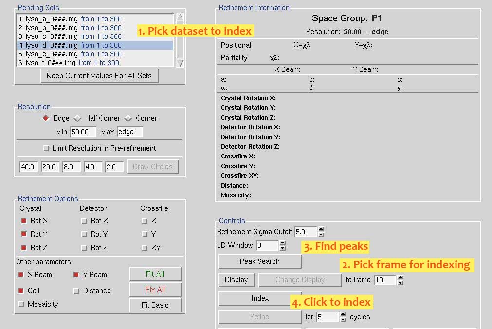
Go to the Index tab and index in four quick steps.
 Upon clicking Peak Seach the image will be shown in a separate window. The red circles indicate identified peaks. There should be at least 100. If very few peaks have been found, you can increase that number by hitting Edit P.S. and then More peaks in the panel on the right. Confirm with OK. You can also use more images for peak finding and then index on a range of images.
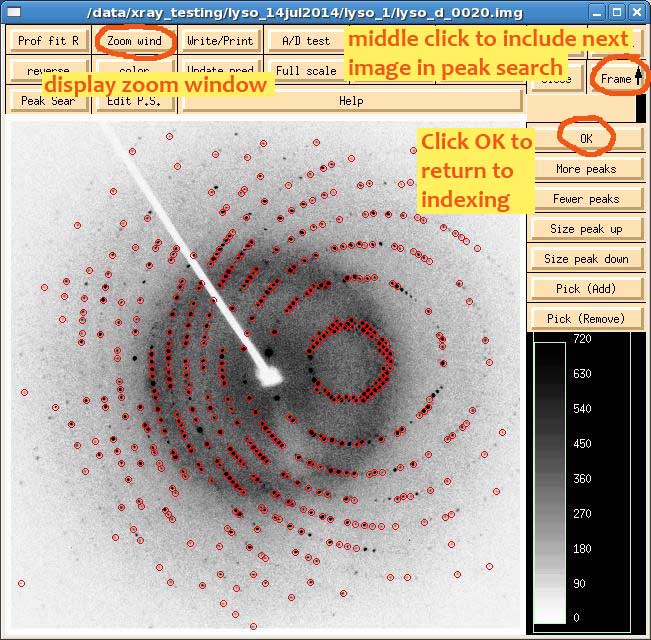
To index on a range of images, middle click the Frame button on the top left of the image window. The first time you do that, you'll have to hit Peak Search on the top right to identify peaks in the new frame, but after that, the software knows what you're trying to do. When you've chosen enough images, confirm by clicking OK, then click Index in the main window. A window will come up with possible Bravais lattices.
Choose the lattice that you know is correct. If you don't know, pick the one with the highest symmetry that still has negligible distortions/errors. This is colour-coded for your convenience. Green is good. Click Apply & Close to return to the Index tab.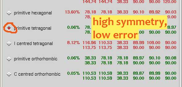
Now's also a good time to display the zoom window by clicking on Zoom Wind in the image window.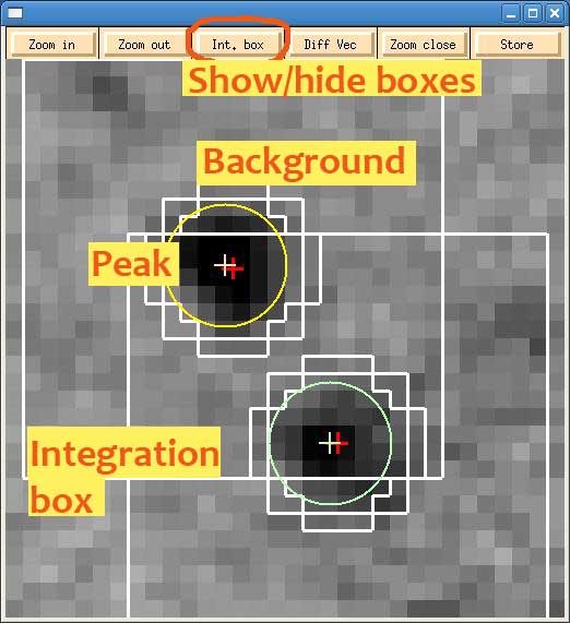
Middle clicking the image redefines the center of the zoomed region. Predictions are indicated by circles. Red means overlap and is bad. Yellow is good. The integration boundary is defined by the inner ragged circumference. The big square minus the outer circumference defines the background. It should be about three times as wide as the spot.
To optimize anomalous signal, the integrated volume should fully cover the peak. This can quickly lead to overlaps on our small detector. To resolve this dilemma, make the background the same size as the spots after clicking More Options in the Integration Box settings.
Postrefinement
Once a satisfying indexing solution has been found, the crystal as well as data collection parameters have to be optimized. This is what postrefinement does.
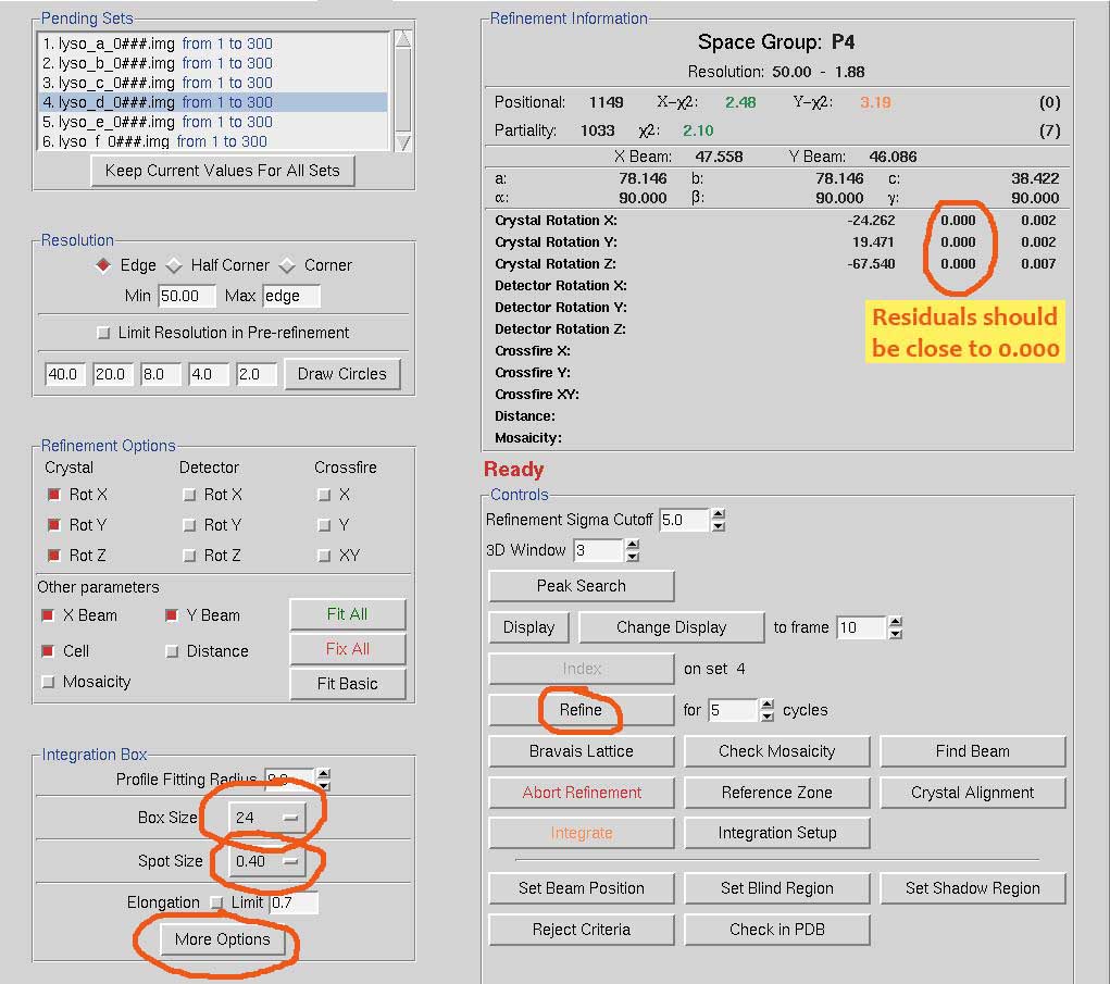
As shown in the figure below, adjust the values of Spot Size and Box Size. The background size can be adjusted, if necessary, through More Options. Hitting Refine refines the parameters selected on the left and updates the image window. Cycle through until the residuals are close to zero. The predictions should be on top of spots.
 Now all parameters are fitted. Click Fit All as shown below and refine some more. All residuals should be close to zero. When you move the mouse into the image window, a circle is shown. This corresponds to the profile fitting radius. Wherever that circle is in the image, it should always have a few predictions inside. If that's not the case, increase the profile fitting radius as indicated in the figure below. Otherwise, profile fitting won't work reliably.
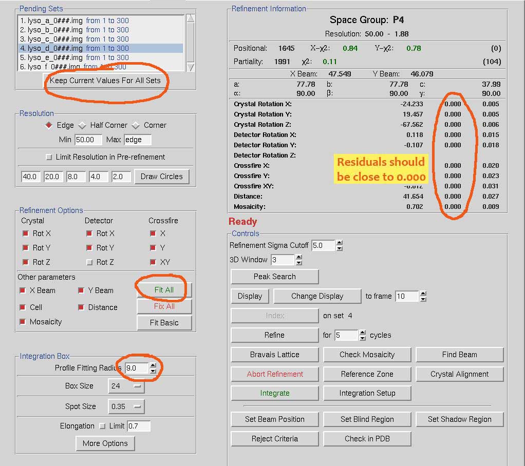 When you're happy with postrefinement, click Keep Current Values For All Sets and continue to integration.

